
Clipper circuits are the electronic circuits that clip off or remove a portion of an AC signal, without causing any distortion to the remaining part of the waveform. These are also known as clippers, clipping circuits, limiters, slicers, etc.
Clipper circuits are basically termed protection devices. Electronic devices are voltage sensitive and large amplitude voltage can permanently destroy the device. So, in order to protect the device clipper circuits are used. The main component of a clipper circuit is a diode or any other type of diode. The diode clips a portion from the input waveform. The shape of the waveform depends on the configuration as well as the design of the circuit. The essential operation of a diode clipping circuit is such that, in forward biased conditions, the diode allows current to pass through it, clamping the voltage. But in reverse biased condition, no current flows through the diode, and thus voltage remains unaffected across its terminals. Usually, clippers employ resistor–diode combinations in their circuitry. Therefore, there are different types of clipper circuits discussed below.
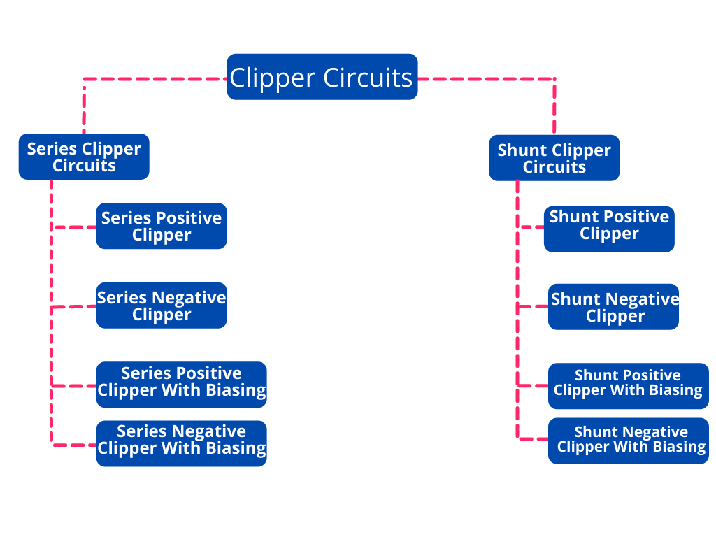
Types of Clipper Circuits
Series Positive Clipper Circuit
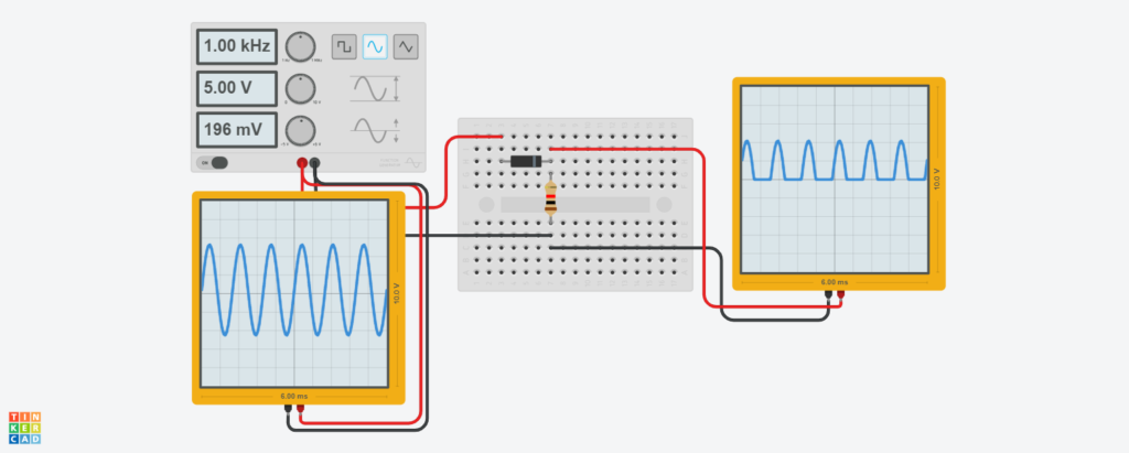
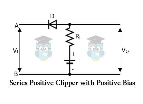
Series positive clippers remove or clip the positive half of the waveform. In a series positive clipper, the diode is reverse biased and in series with the output as shown in the figure below.
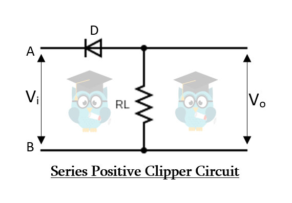
The input signal Vi is applied at the input side while the output is taken at the load resistor. During the positive half cycle of the input, the voltage at point A is more positive than at point B. So the diode is in reverse bias and there is no current conduction. The input signal cannot pass, thus there is no voltage drop at the Rl. Therefore, there the positive half cycle does not appear at the output as shown in the figure.
During the negative half-cycle, the voltage at point A is more negative than at point B. The diode becomes forward biased and the signal passes through it. The signal appears across the Rl. Therefore, the negative half cycle passes through the circuit and appears at the output.
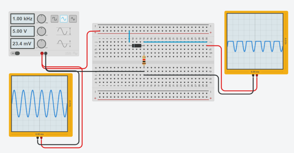
The circuit given below shows how it clips the positive half and allows the negative half of the input waveform.
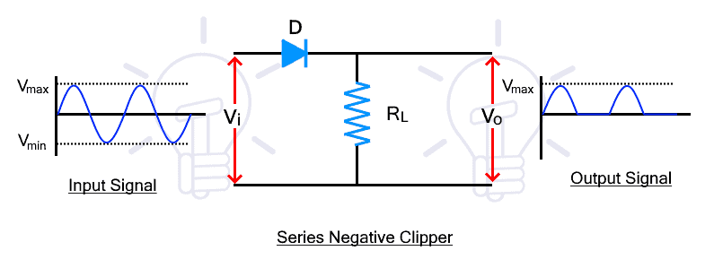
Series Negative Clipper Circuit
The series negative clipper circuit clips the negative half of the input cycle. its circuit diagram is given below.
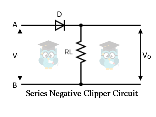
During the positive half cycle, the diode is forward biased due to the input voltage. Therefore, the input signal passes through the diode and appears at the output.
During the negative half cycle, the diode becomes reverse-biased and it does not conduct. Therefore, there is no voltage at the output and the negative half cycle is clipped from the input waveform.
The circuit given below shows how it clips the negative half and allows the positive half of the input waveform.
Series Positive Clippers with Bias
The biasing in the clippers circuit is used to clip a portion of the half-cycle and not the whole halves. Therefore, a series positive clipper with biasing which can be positive or negative is used for producing the desired waveforms.
Positive Bias
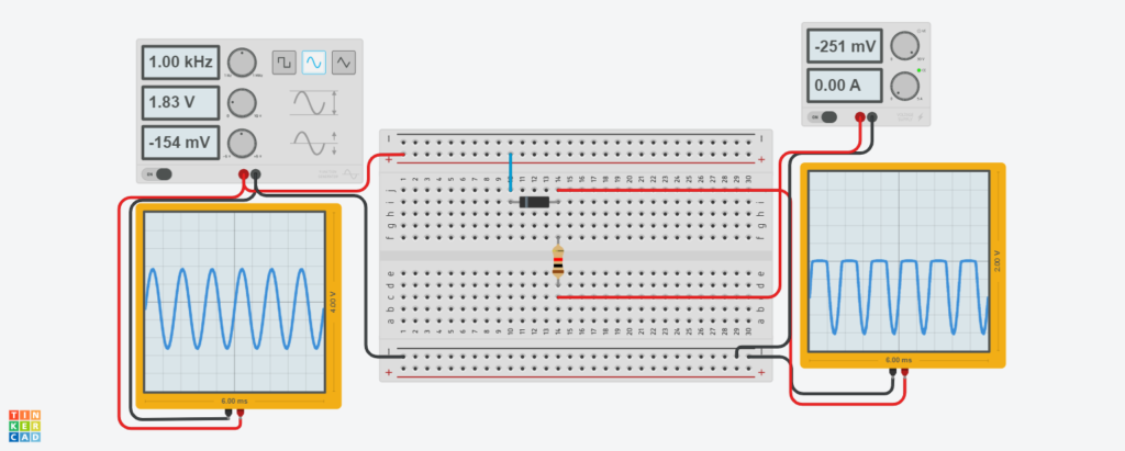
In such a positive clipper circuit with a positive bias, the positive of the battery is connected to the P side of the diode as shown in the figure below.
During the positive half cycle, the voltage at point A is greater than point B due to which, the diode is in reverse bias and switched off. But there is another voltage source whose positive is connected to the P-side of the diode. This voltage source or battery puts the diode in forward bias.
If the input voltage is less than the battery voltage, the diode remains in forward bias and it conducts. Therefore, the signal appears at the output. When the input voltage increases above the battery voltage, the diode becomes reverse-biased and does not conduct the input signal. Therefore, the battery voltage Vb appears at the output.
During the negative half cycle, the diode is forward biased due to the input voltage as well as the battery voltage. Therefore, the input signal passes through the diode and appears at the output.
The battery in the negative biased series positive clipper is connected in reverse with the diode as shown in the figure below.
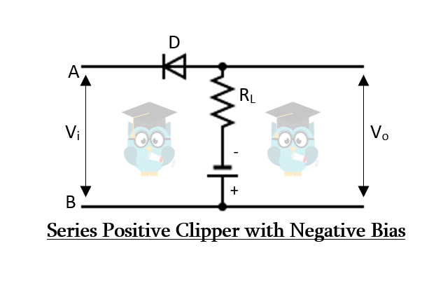
During the positive half cycle, the diode is reversed biased due to the input voltage and the negative battery as well. Therefore, in the positive half cycle, the diode does not conduct and only the negative battery voltage appears at the output.
During the negative half-cycle, the input voltage polarity reverses and the diode becomes forward biased. However, the diode is reverse biased due to the negative battery. Therefore, the diode only becomes forward biased if the input voltage increases above the battery voltage and the input signal appear at the output. Otherwise, the negative battery voltage appears at the output.
Shunt Positive Clipper
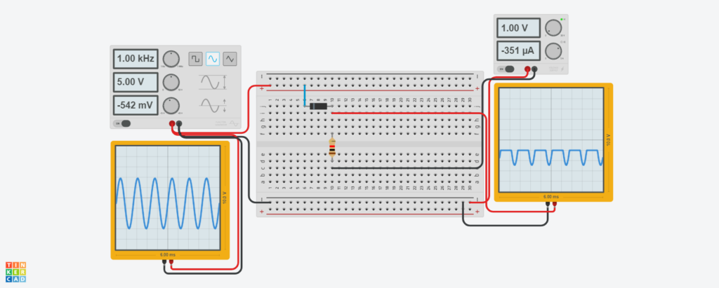
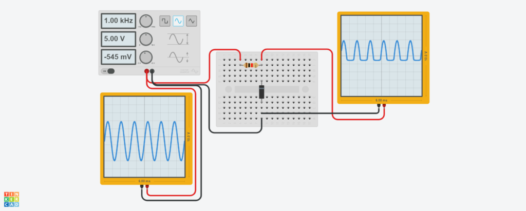
The shunt positive clipper clips the positive half cycle of the input waveform. The circuit diagram of the shunt positive clipper is given below.
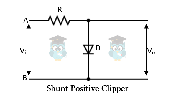
During the positive half cycle, the diode is forward biased as the voltage at point A is greater than point B. so the diode conducts the input signal and there is no voltage difference at the output.
During the negative half-cycle, the voltage polarity of the input signal at points A and B reverses and the diode becomes reverse biased. Therefore, the diode blocks the input signal and the signal voltage appears across the diode that is taken as the output of the clipper.
In such a way, the shunt positive clippers, clips or remove, the positive half of the input cycle and allow the negative half cycle.
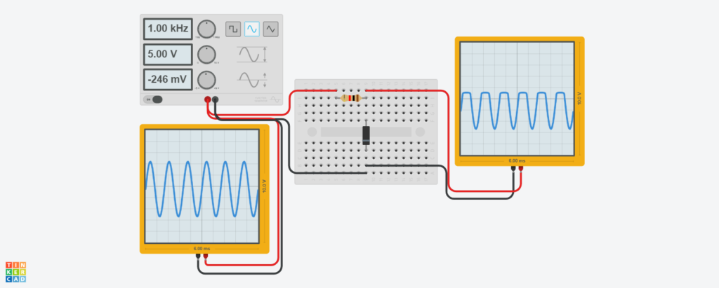
Shunt Negative Clipper
The shunt negative clipper clips the negative half of the input waveform. The circuit diagram is given below.
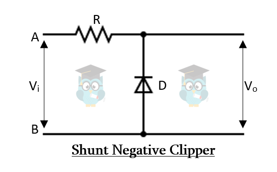
During the positive half cycle, the diode is reversed biased, thus it blocks the signal that appears across it. therefore, the positive half also appears in the output.
During the negative half cycle, the diode is forward biased and it conducts the signal. Therefore, there is no voltage at the output for the negative half cycle. Thus the shunt negative clipper clips or removes the negative half of the input waveform.
Shunt Positive Clippers with Bias
The biasing is done by using another fixed voltage source such as a battery inside the circuit to modify the waveform furthermore. The voltage source can be connected in either positive or negative biasing.
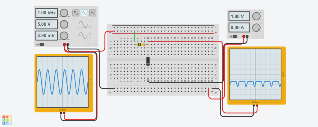
Positive Bias
During the positive half cycle, the diode is forward biased due to the input voltage. but it is reversed biased due to the battery voltage. The sum of both voltages will decide the state of the diode. If the input voltage is greater than the battery voltage, the diode will be forward biased otherwise it will remain in reverse bias.
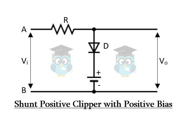
At first, the input signal is less than the battery voltage, so the diode is reversed biased and the signal appears at the output. but when it exceeds the battery voltage, the diode starts conducting the signal and only the battery voltage starts to appear at the output.
During the negative half cycle, the diode is reversed biased due to both input voltage as well as battery voltage. Therefore, the input signal appears for the whole negative half-cycle at the output.

Negative Bias
During the positive half cycle, the diode is forward biased for both input signal and battery voltage. Therefore, the diode conducts for the whole cycle and only the battery voltage appears at the output.
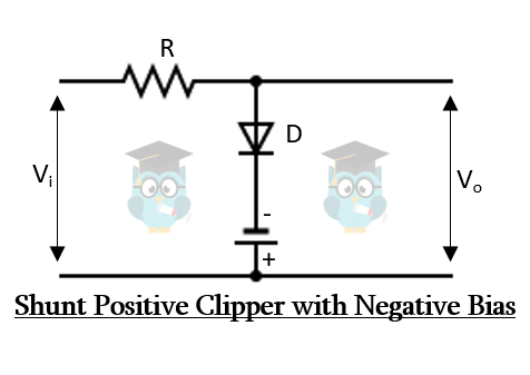
During the negative half cycle, the diode is reversed biased for the input signal and forward biased for battery voltage. The combined effect of both voltage sources decides the state of the diode. The diode is forward biased when the input voltage is less than the battery voltage.
At first, the input signal is less than the battery voltage, thus the diode is forward biased. Therefore, the battery voltage appears at the output. When the input voltage exceeds the battery voltage, the diode becomes reverse biased and the input signal starts to appear at the output as shown in the figure.
Shunt Negative Clippers with Bias
To further modify the waveform of the shunt negative clipper, positive or negative biasing is used with it by connecting a battery source in one of the two ways called positive biasing and negative biasing. The waveform can be modified by varying the voltage of the battery.
Positive Bias
During the positive half cycle, the diode is reversed biased for input voltage but forward biased for battery voltage. So, the diode will be reversed biased only when the input voltage exceeds the battery voltage and then the input signal will appear at the output.
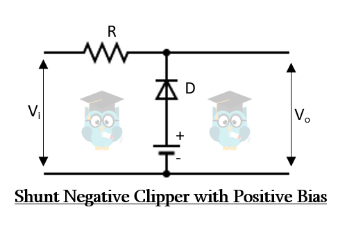
At first, the signal is less than the battery, so the diode is forward biased and it conducts the signal. Therefore, only the battery voltage appears at the output. but when the input signal exceeds the battery voltage, the diode becomes reversed biased and the signal appears at the output as shown in the figure.
During the negative half cycle, the diode is forward biased for both input signal and battery voltage. Therefore, the diode conducts and only the battery voltage appears at the output for the whole negative cycle.

Negative Bias
During the positive half cycle, the diode is reversed biased for both input and battery voltage. thus, the diode blocks the voltage and the signal appears at the output for the whole positive half cycle.
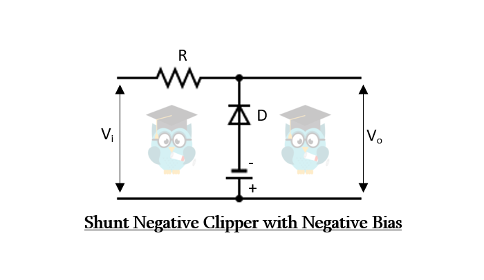
During the negative half cycle, the diode conducts when the input voltage exceeds the battery voltage. Therefore, when the voltage is less than the battery voltage, the diode blocks and the signal appears at the output. When the input voltage exceeds, the diode starts conduction and only the battery voltage appears at the output.